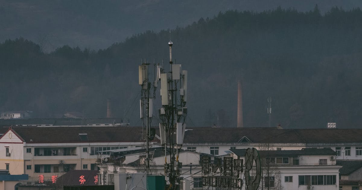
Where should counter-UAS radar be installed? There is no single correct answer. Airports, industrial sites, energy facilities, ports, borders, campuses, and temporary events all have different terrain, buildings, vegetation, roads, and restricted areas. The right radar position depends on the mission and the local environment.
A more useful rule is this: install the radar where it can maintain stable visibility over the important low-altitude corridors, cover the boundary of the protected area, reduce obstruction and clutter, and still support power, networking, safety, and maintenance.
Start With the Asset and the Threat Direction
The first step is not to find the tallest structure. It is to define what must be protected. Where is the critical asset? From which directions could a drone approach? Which areas require early warning, and which areas only require close-in confirmation? Are there exclusion zones, buffer zones, response zones, or crowded public areas?
If the protected asset is a fixed campus, radar may be better placed near the perimeter or near the most likely approach direction. That gives operators more time to confirm and respond before the drone reaches the core area. If the protected object is a central facility in open ground, a central high point may provide more balanced coverage.
When a site has obvious risk corridors, such as a river, road, valley, open field, coastline, or gap between buildings, radar placement should prioritize those low-altitude paths.
Low-Altitude Line of Sight Matters More Than Map Distance
Counter-UAS radar is designed to find small targets at low altitude. A location that looks close on a map may be blocked by buildings, walls, trees, terrain, cranes, billboards, storage tanks, or heavy equipment. Small drones may fly at tens of meters or even lower, so obstruction has an immediate effect on detection.
For that reason, site planning must examine the line of sight between the radar antenna and the target airspace. Horizontal distance is not enough. Site elevation is not enough. A radar can have a clear view of the sky but still miss the most important low-altitude corridor because a nearby structure blocks it.
A good survey combines maps, building heights, terrain data, on-site inspection, and coverage modeling. In complex environments, the design should be verified with test flights or standard targets rather than accepted only from a desktop study.
Height Helps, but It Is Not the Only Goal
Increasing installation height can reduce local obstruction, extend low-altitude visibility, and help the radar see approaching drones earlier. Rooftops, fixed masts, communication towers, trailers with lifting masts, and dedicated towers can all be valid platforms.
But higher is not always better. If the radar is too low, it may be blocked. If it is too high, near-zone geometry can become less favorable, the area directly around or below the radar may need extra coverage, and the structure may create challenges for load, wind, lightning protection, cable routing, and safe maintenance.
In real projects, the correct height is usually a compromise. It should clear key obstructions while preserving near-area coverage, structural safety, service access, and long-term reliability.
Avoid Severe Clutter and Local Interference
Radar sees the environment as well as the drone. Large metal structures, moving machinery, busy roads, swaying trees, water surfaces, cranes, rotating equipment, and reflective buildings can all increase clutter and create extra work for filtering and alarm management.
This does not mean the radar must be placed in a perfect empty field. Many real deployments are at ports, airports, industrial parks, and urban edges. However, the radar should not be aimed directly into severe reflectors or constant moving clutter if there is a better option.
Placement, antenna orientation, masking zones, clutter filters, alarm rules, and EO/IR confirmation can all help. Planning should also consider future changes: construction, seasonal vegetation, parking patterns, new buildings, and temporary event structures may change the radar view.
Plan Radar Together With EO/IR and RF Sensors
Counter-UAS radar rarely works alone. It usually sends tracks to an EO/IR camera for visual confirmation and may also integrate with RF detection, a command platform, alarm systems, and mitigation equipment. Radar placement should therefore be planned as part of the whole system.
If radar detects a target but the camera is blocked by a building, confirmation becomes slower. If the radar site has unstable network access, good coverage will not translate into reliable operations. If power, grounding, and lightning protection are weak, long-term availability will suffer.
A strong design considers radar, EO/IR, RF sensors, networking, power, grounding, lightning protection, maintenance access, and operator workflow at the same time.
Use Additional Radars When One Point Cannot Cover the Site
Many sites cannot be covered well by a single radar. Building clusters, hills, port equipment, tree lines, and complex perimeters often create low-altitude blind spots. In those cases, the better answer may be multiple radars, added coverage for priority sectors, or a combination of fixed and mobile systems.
Multi-radar deployment is not simply a matter of adding more devices. It requires planning for overlap, track fusion, time synchronization, sensor naming, alarm zones, and maintenance ownership. Otherwise, several radars may create duplicate alarms and make the operator’s job harder.
For critical areas, controlled overlap is useful. A target seen from two directions is often easier to track and classify, and the system becomes less vulnerable to one local obstruction.
Acceptance Should Test the Real Mission
After installation, acceptance should not stop at power-on checks and platform connectivity. The important question is whether the site can detect, track, confirm, and report targets in the required areas.
Useful acceptance checks include:
- Standard target tests along priority approach paths
- Flight records at different heights, ranges, and routes
- Identification of blind spots and weak coverage zones
- EO/IR handoff and visual confirmation tests
- False alarm statistics in normal clutter conditions
- Network, power, grounding, lightning, and service access checks
- Review of alarm zones and response workflow
These tests reveal issues that a planning drawing may miss and provide a baseline for tuning and future upgrades.
Conclusion
Counter-UAS radar placement should be driven by the protected asset, low-altitude line of sight, obstructions, clutter, likely approach directions, sensor integration, and maintainability. The highest point is not automatically the best point, and the nearest point is not automatically the most useful.
The reliable method is to define the protected zones and risk directions, perform a site survey and coverage design, and then verify the result with real testing. In complex locations, multiple radars and blind-spot coverage are normal engineering tools, not signs that the first radar failed.