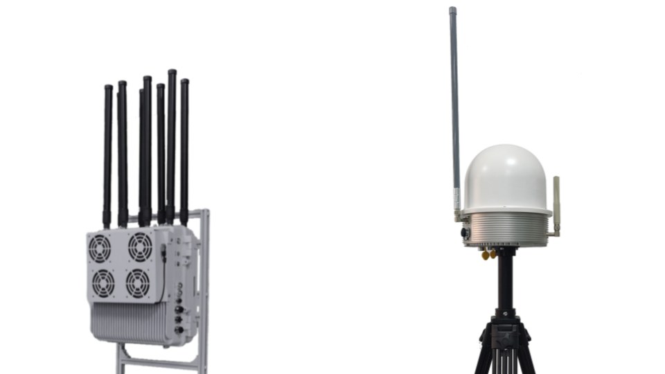
RF systems are often discussed as if detection coverage and bearing quality were mainly determined by chipset class, algorithms, or nominal antenna specifications. Those things matter, but placement often matters first. Once an antenna or antenna array is installed in a real site, the local geometry begins shaping which signals arrive, which paths dominate, and whether the measurement still reflects the emitter or mostly reflects the environment.
This matters even more for multi-sensor security and counter-UAS work because RF installations are frequently placed on rooftops, masts, corners of industrial sites, or utility structures that were not originally designed for clean radio geometry. The result is that an excellent antenna system on a poor site can become a weak detector, a misleading bearing source, or both.
The useful question is therefore not only “What antenna are we using?” It is “What measurement conditions did the installation create?” Once that question is asked, height, clutter, reflections, sector ownership, and calibration become central design issues instead of late-stage surprises.
Placement Shapes the RF Problem Before Processing Begins
Bluetooth’s range guidance offers a simple but powerful framing: effective range depends on transmitter power, receiver sensitivity, antenna gain, and path loss. That principle applies far beyond Bluetooth. The moment an RF system is placed in a real site, the path-loss environment and effective antenna behavior become deployment variables rather than datasheet abstractions.
For a fixed monitoring site, placement affects:
- which sectors are shadowed,
- where reflections dominate,
- how strong the direct path remains,
- and whether the system sees a clean arrival direction or a distorted one.
This is why two nominally identical receivers can behave very differently at different corners of the same site. One may have a clear view of likely approach corridors. Another may sit near rooftop clutter, parapets, HVAC units, cranes, or metal railings that distort the field before the receiver ever processes the signal.
From a system-design standpoint, placement is therefore not the final physical step. It is part of the signal chain.
More Height Usually Improves Horizon, but It Does Not Solve Everything
Height is one of the first variables people reach for, and for good reason. Raising an RF antenna often improves line of sight, extends practical horizon, and reduces low-level masking by walls, vehicles, berms, or vegetation.
That is especially useful when the system’s main job is broad RF detection coverage over open sectors. A higher placement can increase the chance that weak or distant signals arrive above local obstacles rather than through them.
But more height is not automatically better for every task.
In bearing systems, a higher placement can also introduce:
- different reflection geometry from nearby surfaces,
- more exposure to adjacent structures,
- longer feedline complexity depending on architecture,
- and sectors where the antenna sees too much cluttered environment rather than less.
The right question is not just “How high can we mount it?” The right question is “What viewing volume and propagation environment does this height create?” A moderate height with clean sector ownership can outperform a taller but more cluttered position.
Nearby Metal and Site Clutter Change Both Detection and Bearing
RF antennas do not operate in isolation once installed. Nearby conductive surfaces and structures can reshape patterns, create shadowing, and introduce reflections that alter what the receiver believes it is seeing.
This matters for simple detection coverage, because local clutter can weaken the direct path or bias which sectors are easiest to hear. It matters even more for direction finding, because a clean-looking angle estimate may actually represent a reflection-dominated arrival path.
The Sensors review of Bluetooth 5.1 direction-finding capability is useful here because it emphasizes that array design is not trivial, that mutual coupling matters, and that accurate angle estimation depends on the quality of the IQ data collected across the array. Those issues become harder, not easier, when the installed environment perturbs the array’s intended behavior.
In practical site terms, risky placements often include locations:
- near large metal housings,
- tight against parapets or equipment shelters,
- beside reflective rooftop plant,
- or in corners where several structures create repeatable echo paths.
The antenna may still work there. But the site should assume it needs validation, not trust.
Bearing Accuracy Depends on Array Integrity, Not Only on Coverage
When the system needs bearings rather than just presence detection, placement constraints become stricter.
Angle-of-arrival systems depend on stable relationships across the receiving elements. If the placement environment or installation quality disturbs those relationships, the bearing can degrade even when the signal is still strong enough to detect.
That is why array installations should protect:
- geometry symmetry,
- cable integrity and length discipline where relevant,
- mounting rigidity,
- orientation reference,
- and consistent exposure of the array to the intended observation sectors.
The in-situ calibration literature is especially relevant here. Research on antenna-array calibration for positioning shows that direction-estimation performance can degrade severely when real installation errors and array perturbations are left uncorrected. That is not only a laboratory problem. It is a site problem, because installation changes and structural context alter the array the algorithms think they are using.
So for DF-capable systems, antenna placement is not just about hearing the signal. It is about preserving the geometry required to interpret the signal correctly.
Sector Ownership Matters More Than Average Site Coverage
One of the weakest design habits in RF siting is to talk about the site as if one coverage number or one average bearing accuracy tells the whole story.
Real sites rarely behave that uniformly. Some sectors may be open and clean. Others may be dominated by rooftop structures, nearby towers, metal facades, utility lines, or waterfront reflections. A site can therefore have:
- excellent performance in one direction,
- mediocre performance in another,
- and large occasional outliers in a third.
This is why placement should be evaluated sector by sector. A system may need more than one RF site not because the hardware is poor, but because one physical location cannot own the whole volume honestly. That is especially true when the protected area has irregular geometry or when likely emitter paths come from several different elevations and azimuths.
Sector-based planning also improves fusion design. If the team knows which sectors have strong DF trust and which are only detection-capable, the platform can use those sectors differently instead of treating every bearing as equally strong.
Cables, Mounting, and Maintenance Changes Can Quietly Degrade Performance
Some RF placement problems appear only after installation.
An antenna or array may initially perform well and then drift because:
- a cable is replaced,
- a mast is reworked,
- nearby metal is added,
- a rooftop unit is installed,
- or the structure’s tilt or mechanical condition changes.
Direction-finding literature repeatedly points to calibration and array characterization as essential to maintaining performance. That matters operationally because many field problems are introduced by normal maintenance rather than by obvious sensor failure. The hardware still powers on, the software still produces detections, and the bearing still looks numerically precise. But the installation is no longer the same one that was originally characterized.
This is why good RF deployments keep records of:
- installed orientation,
- cable changes,
- array servicing,
- major nearby structural changes,
- and calibration history.
Without that discipline, the site may not know when the sensor’s geometry changed from trustworthy to merely plausible.
Validate Placement After Installation, Not Only Before
Pre-installation surveys are necessary, but they are not enough.
Once the antenna is physically mounted, the site should validate:
- detection consistency by sector,
- weak-signal behavior where coverage margins are small,
- bearing bias and spread where DF is expected,
- and performance changes under likely cluttered or reflective conditions.
This is where simple field testing often reveals what the site model missed. A sector that looked open on a plan may show repeatable reflections. A supposedly secondary rooftop structure may dominate one azimuth. A convenient mast may create near-field issues for low-altitude or close-in emitters.
The strongest acceptance process therefore does not ask only “Did the system detect the signal?” It asks:
- from which sectors,
- with what repeatability,
- under what installation state,
- and with what confidence in the resulting angle or coverage claim.
That is what turns placement into a measurable engineering parameter instead of a hopeful assumption.
Common Placement Mistakes
Several installation errors repeatedly damage RF performance.
Choosing convenience over sector quality
The easiest mast or rooftop corner is not always the cleanest RF site.
Assuming higher is always better
Height helps many cases, but it can also create new reflection and integration problems.
Placing arrays too close to metal clutter
This can distort both coverage and phase-based or pattern-based bearing behavior.
Ignoring post-installation changes
A site can silently degrade when cables, structures, or mounting conditions change.
Evaluating by site-average performance
Average numbers hide the bad sectors that often matter most operationally.
Trusting laboratory behavior without field validation
The installation environment is part of the RF system and has to be tested as such.
Conclusion
RF antenna placement changes detection and bearing accuracy because the installation itself shapes the signal conditions the receiver must interpret. Height, masking, nearby metal, array integrity, and sector geometry all influence whether the system hears the signal well and whether it can assign that signal to a trustworthy direction.
The practical takeaway is straightforward. Treat placement as part of the measurement chain, not as a last-mile mounting choice. Plan by sector, validate after installation, and revisit performance whenever the physical environment changes. That is how RF systems stay believable in real sites.
Related Reading
- What Makes an RF Bearing Trustworthy in Real Sites?
- AOA vs TDOA vs FDOA: Which RF Geolocation Method Fits Which Project?
- Remote ID Reception Range: What Actually Changes It?
Further Reading
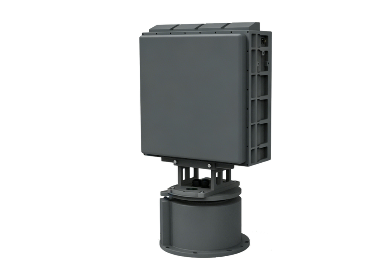
Need Counter-Drone Radar for Your Site?
CR series low-altitude surveillance radars detect RCS 0.01 m² drones at 3–10 km and classify targets by micro-Doppler — every track outputs with target class and confidence.